DXF
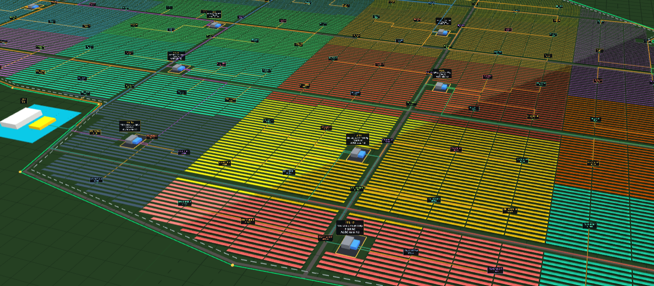
Tables, roads, trenches, station numbers and field tags on separate layers, ready to drop into your own drawing set.
A CADDEZ product
Utility-scale solar layout, electrical design and bill of quantities — in the browser. From a DXF boundary to a construction-ready layout, cable schedule and BOQ. No installation, no CAD seat, no plugin to maintain.
Every step below is real work someone in a drawing office does today, and almost all of it has to be repeated when an input upstream moves.
Six steps, in order. Each one feeds the next, which is why changing an early input re-resolves everything downstream rather than orphaning it.
Parcel as DXF. The coordinate system is read from GEODATA and verified against a basemap, so you can see the site landed where it should before anything is drawn.
The full array set out against real parcel geometry — boundary, roads, setbacks and terrain, not an idealised rectangle.
Tables packed into inverter stations to rating, then tagged consistently so the same table carries the same reference in the 3D view, the DXF and the BOQ.
SCB and MV cable routed along shared trench corridors, with run lengths measured on the model rather than estimated from a factor.
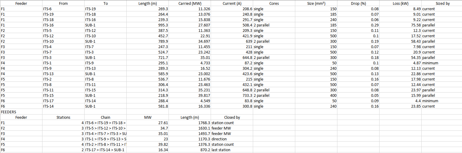
Every run sized automatically, with voltage drop, loss and the sizing basis stated for each circuit — by current, by parallel set, or at minimum section.
DXF, cable schedule, pile setting-out sheet and BOQ — all generated from the layout that was actually built.
The same 211.76 MWp site, the same 19 inverter stations, the same 4,870 tables — designed once radially, then once as a looped RMU ring. Both runs took about twenty minutes.
| 211.76 MWp DC · 131.66 ha · 33 kV aluminium | Radial | Looped RMU | Change |
|---|---|---|---|
| MV feeder panels | 19 | 6 | −13 |
| MV cable | 22.1 km | 11.4 km | −10.8 km |
| MV loss | 631.5 kW | 412.3 kW | −219 kW |
| Worst voltage drop | 0.75% | 0.29% | −0.46 pt |
The cable schedule exports circuit by circuit with the sizing basis stated for each run. The feeder summary states why each feeder terminated where it did — station count, feeder MW, direction, or last station — so a reviewer can follow the logic rather than take the total on faith.
Tables, roads, trenches, station numbers and field tags on separate layers, ready to drop into your own drawing set.
DC and MV, with sizing basis, voltage drop and loss stated for every run.
Latitude and longitude, ground level, reveal and ordered pile length — ready for the survey team.
CADDEZ has spent 5 years on AutoCAD-based drafting automation and PEB detailing for steel fabricators, manufacturers and EPC teams across the World.
That is time spent inside the drawing workflows utility-scale solar depends on — and building the automation that removes the repetitive parts of them. SolarCAD is that experience applied to one problem, end to end.
Evaluation
Send a parcel from your pipeline and we will run it with you on a call. You keep the DXF, the cable schedule and the pile setting-out sheet either way — the point is for you to judge it on your own geometry rather than our demo site.